|
|
Information
| 说明: |
建议参照本版块置顶帖内容输入必要信息 |
| 芯片型号: |
TLSR8251 |
| 驱动SDK版本: |
B85m_BLE_Single_Connection_SDK_v3.4.2.1 |
本帖最后由 wx_4955935040 于 2024-9-5 14:13 编辑


void adc_gpio_ain_init(void)
{
//set misc channel en, and adc state machine state cnt 2( "set" stage and "capture" state for misc channel)
adc_set_chn_enable_and_max_state_cnt(ADC_MISC_CHN, 2); //set total length for sampling state machine and channel
//set "capture state" length for misc channel: 240
//set "set state" length for misc channel: 10
//adc state machine period = 24M/250 = 96K, T = 10.4 uS
#if (MCU_CORE_TYPE == MCU_CORE_8278)
adc_set_state_length(240,10); //set R_max_mc,R_max_c,R_max_s
#else
adc_set_state_length(240, 0, 10);
#endif
//set misc channel use differential_mode (telink advice: only differential mode is available)
//single mode adc source, PB4 for example: PB4 positive channel, GND negative channel
gpio_set_func(GPIO_PC4, AS_GPIO);
gpio_set_input_en(GPIO_PC4, 0);
gpio_set_output_en(GPIO_PC4, 0);
gpio_write(GPIO_PC4, 0);
#if(MCU_CORE_TYPE == MCU_CORE_827x)
adc_set_ain_channel_differential_mode(B4P, GND);
//set misc channel resolution 14 bit
//notice that: in differential_mode MSB is sign bit, rest are data, here BIT(13) is sign bit
adc_set_resolution(RES14); //set resolution
//set misc channel vref 1.2V
adc_set_ref_voltage(ADC_VREF_1P2V); //set channel Vref
//set misc t_sample 6 cycle of adc clock: 6 * 1/4M
adc_set_tsample_cycle(SAMPLING_CYCLES_6); //Number of ADC clock cycles in sampling phase
#elif(MCU_CORE_TYPE == MCU_CORE_825x)
adc_set_ain_channel_differential_mode(ADC_MISC_CHN, C4P, GND);
//set misc channel resolution 14 bit
//notice that: in differential_mode MSB is sign bit, rest are data, here BIT(13) is sign bit
adc_set_resolution(ADC_MISC_CHN, RES14); //set resolution
//set misc channel vref 1.2V
adc_set_ref_voltage(ADC_MISC_CHN, ADC_VREF_1P2V); //set channel Vref
//set misc t_sample 6 cycle of adc clock: 6 * 1/4M
adc_set_tsample_cycle(ADC_MISC_CHN, SAMPLING_CYCLES_6); //Number of ADC clock cycles in sampling phase
#endif
//set Analog input pre-scaling 1/8
adc_set_ain_pre_scaler(ADC_PRESCALER_1F8);
}
void adc_gpio_ain_init_test(void)
{
//set misc channel en, and adc state machine state cnt 2( "set" stage and "capture" state for misc channel)
adc_set_chn_enable_and_max_state_cnt(ADC_MISC_CHN, 2); //set total length for sampling state machine and channel
//set "capture state" length for misc channel: 240
//set "set state" length for misc channel: 10
//adc state machine period = 24M/250 = 96K, T = 10.4 uS
#if (MCU_CORE_TYPE == MCU_CORE_8278)
adc_set_state_length(240,10); //set R_max_mc,R_max_c,R_max_s
#else
adc_set_state_length(240, 0, 10);
#endif
//set misc channel use differential_mode (telink advice: only differential mode is available)
//single mode adc source, PB4 for example: PB4 positive channel, GND negative channel
gpio_set_func(GPIO_PC5, AS_GPIO);
gpio_set_input_en(GPIO_PC5, 0);
gpio_set_output_en(GPIO_PC5, 0);
gpio_write(GPIO_PC5, 0);
#if(MCU_CORE_TYPE == MCU_CORE_827x)
adc_set_ain_channel_differential_mode(B4P, GND);
//set misc channel resolution 14 bit
//notice that: in differential_mode MSB is sign bit, rest are data, here BIT(13) is sign bit
adc_set_resolution(RES14); //set resolution
//set misc channel vref 1.2V
adc_set_ref_voltage(ADC_VREF_1P2V); 设置通道 Vref
设置其他 t_sample ADC 时钟周期:6 * 1/4M
adc_set_tsample_cycle(SAMPLING_CYCLES_6); 采样阶段的 ADC 时钟周期数
#elif(MCU_CORE_TYPE == MCU_CORE_825x)
adc_set_ain_channel_differential_mode(ADC_MISC_CHN,C5P,GND);
设置杂项通道分辨率 14 位
注意:differential_mode MSB 是符号位,其余是数据,这里 BIT(13) 是符号位
adc_set_resolution(ADC_MISC_CHN,RES14);设置分辨率
设置杂项通道 VREF 1.2V
adc_set_ref_voltage(ADC_MISC_CHN, ADC_VREF_1P2V); 设置通道 Vref
设置其他 t_sample ADC 时钟周期:6 * 1/4M
adc_set_tsample_cycle(ADC_MISC_CHN, SAMPLING_CYCLES_6); 采样阶段的 ADC 时钟周期数
#endif
设置模拟输入预缩放 1/8
adc_set_ain_pre_scaler(ADC_PRESCALER_1F8);
}
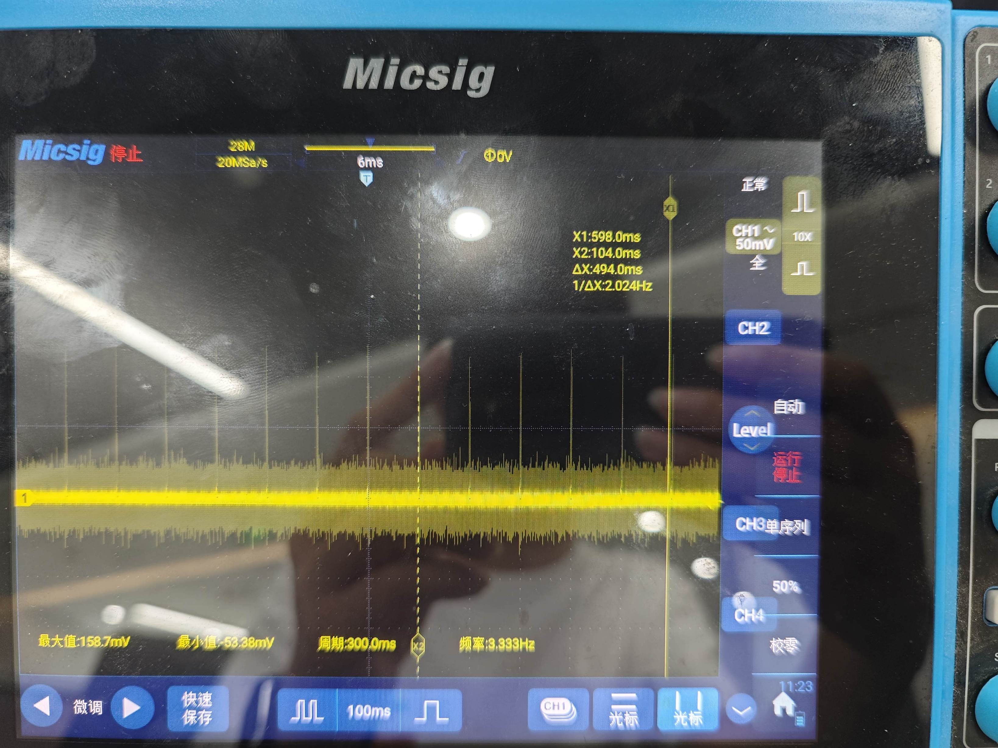
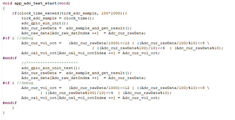
用的sdk下b85m_driver_test/app_adc.c,在源码基础上增加了一个引脚的ADC采样,即同时采C4/C5,断开硬件电路,交流挡测C5引脚会出现图片中的峰刺。是否有解决办法
|
|